Knowledge is knowledge

Showing posts with label Electronic Devices and Circuits. Show all posts

Introduction to Field Effect Transistors (FET's) also similarity and difference

 Introduction to Field Effect Transistors (FET's)  also similarity and difference

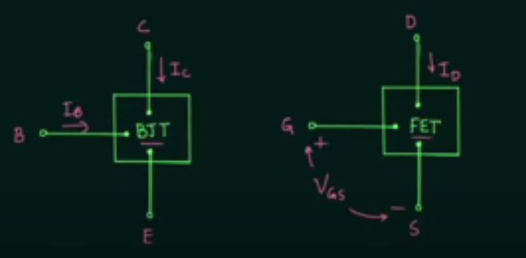
  • BJT and FET Both are 3 terminal devices
  • BJT and FET's have nearly equal importance.
  • BJT is a current-controlled device while FET's are voltage-controlled devices its the main difference between them. ( Ic=f(Ib) and Id = f(Vgs) )
  •  BJT is a bipolar device and FET's are unipolar devices.
  • FET's are of two types n -channel FET's and p-channel FET's.
  •  FET's can be used as amplifiers or switches.
  •  FET's are classifieds into two categories JFET and MOSFET
  • JFET is classified into two categories n -channel and p- channel.
  •  MOSFET is classified into DMOSFET and EMOSFET. and bother of them further divided into two categories n-channel and p-channel.
  • FET's are known as Field effect transistors because there is an electric field is developed by the charge is present and this electric field controls the conduction path of the output circuit.So there is an effect of electric field and so this device is known as Field effect transistors.
  • Input impedance: FET's have higher input impedance as compared to BJT's
  • FET's are more temperature stable then BJT.
  •  FET's are smaller then BJT.
  •  BJT's are more sensitive to the applied signal as compared to the FET's.


Share:

T - model of BJT ( small - signal model development of BJT )

we can use BJT in both the cases of small signal and large signals for the amplification of them, when we deal with the smaller amplitude signals and try to amplify them then the term small-signal model development of BJT and small-signal analysis of BJT comes into the picture.

Small signal model

when we biased the BJT then we try to analyze the BJT for the small-signal operation so we feel a need for replacement of BJT with some simple electrical circuit for easy dealing we chose the components as they give the same functionality as BJT and then we analyze them for small signals. The simpler circuits are referred to as the small-signal models of BJT.

Here in this article, we deal with T - model of BJT it is called by this name because it looks like T shape

T - model of BJT ( small - signal model development of BJT )

Although the hybrid pi model of BJT is simple and very well used for the analysis of the amplifiers, yet the other variant of the model is more convenient in some situations. This variant is called the T - model,


if we rotate the figure by 90 degree we see that it appears like T so it is called the T model of BJT


Writing KCL at the base point in the following figure (a)


The base current drive should have the input resistance r pi; which comes out from this derivation


                                           fig: The T model of BJT with ro

Share: